When the Wind Won't Whirl - or the real reason the Whirlwind suffered at height.
THE UNCONVENTIONALLY pretty Westland Whirlwind has always attracted controversy. For some it was a world-beater that was unfairly cancelled in its prime, while others see it as a lame duck that should never have left the drawing board. One thing that both sides agree on is that it was let down by its engines, an apparent rare mistake by Rolls-Royce called the Peregrine. This is almost certainly wrong.
The first person to make this claim in writing was perhaps the Whirlwind’s own “famously difficult” designer, William Edward Willoughby “Teddy” Petter. In November 1940 he came back to Yeovil from a visit to No 263 Sqn, which was working up on the radical new fighter in Scotland, claiming to have discovered that, unlike the prototype, his creation was suffering from a fall-off in supercharger boost with altitude at “twice the rate anticipated”.1 Conveniently ignoring how unlikely this was in his efforts to absolve his design from blame for its failings, he painted a picture of an aircraft that progressively became slower and more useless at anything above a full-throttle height of 15,800ft (4,815m), thanks entirely to the “third-party” engines.2
A potential game-changer
This seemed a great pity. Down low nothing could catch a Whirlwind. It was manœuvrable, practically viceless and rapidly becoming beloved by its pilots. It certainly should have been a game- changer. As a weapon of war it was formidably potent, with four 20mm cannon packed close together in the nose. Aimed by looking straight down the barrels, these could take out a tank at a time when nothing else flying could. The Whirlwind was also innovative; it had a bubble canopy, intakes in the leading edges, slats and Fowler flaps. It had a slab-sided fuselage over the wing, which almost nobody noted at the time (or since) was the ultimate solution to high- speed interference drag.
So how could Rolls- Royce allow it to be pole-axed so disastrously? The probable answer is that it didn’t. Back in July 1940 the RAF’s acceptance testing team at Martlesham Heath had given the aircraft a clean bill of health and a ceiling of 31,000ft (9,450m).3 However, as the first trickle of Whirlwinds began to arrive with Nos 25 and 263 Sqns in 1940, service pilots began to ask why the altitude performance wasn’t what it should have been, or even what it was when tested. The question escalated to the Chief Technical Officer of Fighter Command, Gp Capt Beardsworth, who evidently telephoned E.J. Jones, Chief Technical Officer at the Aeroplane & Armament Experimental Establishment (A&AEE) at Martlesham Heath, on October 25, 1940, asking him, in the light of the poor altitude performance, what was different between production machines and the prototype tested there, L6845.1
Although the telephone call wasn’t logged, the written reply is very telling: “Whirlwind; In reply to your telephone query of today, the following information is available.
- Our trials were conducted at an all-up weight of 10,072lb [4,569kg] and this represents the present maximum full load for the aeroplane;
- The aeroplane we tested was L6845 and this was the first production aeroplane;
- The estimated service ceiling is 30,300ft [9,235m] and the absolute ceiling is 31,000ft.”

Elsewhere, Eric Mensforth, the Managing Director of Westland, had stated that L6845 was “identical to a production Whirlwind”.1 Nowhere was it recorded that the “first production aeroplane” (in fact the second prototype) had very different propellers. An important distinction Remarkably, the prototype sent by Westland to Martlesham Heath as a representative of the production model was fitted with propellers of a one-off Rotol design (right), not the de Havilland (DH) props hung on all subsequent production Whirlwinds (left). Amazingly, nobody (at least at Westland or the A&AEE) seemed to think that this mattered. In the hundreds of pages of records, letters, memos and reports between the RAF, Air Ministry and Westland, including documents which discuss the difference between “handed” and “non-handed” props, and which go into incredible detail about minor changes desired and applied during development, this major change goes completely unmentioned.
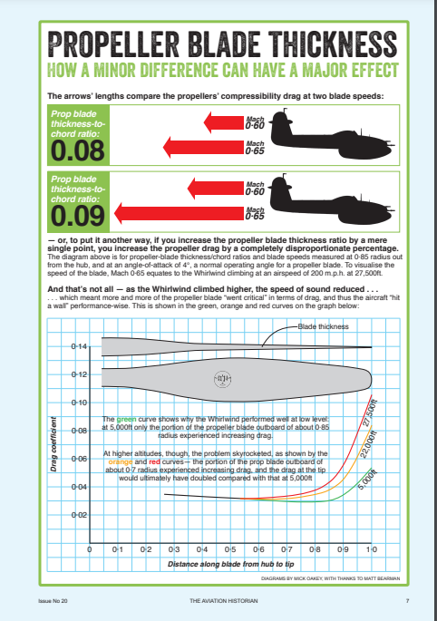
One thing that stands out about the standard Peregrine “power egg” — a phrase that may have been coined by Mensforth when discussing the Whirlwind — is that its DH propeller blades are remarkably thick for a high-performance fighter. According to the few DH specifications that are still available at Farnborough, the thickness to chord (t/c) ratio at 0·7 radius is around 0·096.4 For comparison, the propeller used on the Supermarine Spitfire I had very similar-profile DH blades — of type 55409 as opposed to the Whirlwind’s type 54409 — but with a crucial difference; a t/c ratio of 0·076 at 0·7 radius
The science of propellers is arcane and difficult. Although propellers are the only means of translating an engine’s power into motion, the things that make a difference between almost all and almost none of that horsepower actually being applied rapidly descend into very hard sums indeed. Perhaps this is the reason they get overlooked so often.
Another tricky area is compressibility. This was first encountered when the ungeared propellers of high-revving engines began pulling themselves through the air at forward speeds that meant the combined velocity of their rotation and forward motion began creeping towards a significant proportion of the speed of sound. That significant proportion is in fact “critical Mach” — the speed at which at least some of the air passing by an object is moving at or above the speed of sound relative to it. An aerofoil accelerates the air passing over it; propeller blades are aerofoils and become the first part of an aeroplane to hit critical Mach. This they started doing regularly in the 1920s, and the first thing that was noticed was the aircraft’s reluctance to go any faster. The second was the appalling noise, familiar to anybody who has heard a North American Harvard take off.
A question of thickness
This became an area for urgent investigation on both sides of the Atlantic. In the USA the National Advisory Committee for Aeronautics (NACA) commissioned research using the very latest in windtunnel technology at its Langley facility in Hampton, Virginia. Stepping up to the plate was the brilliant young aerodynamicist John Stack. Later it was to be Stack who solved the compressibility problems built into the Lockheed P-38 (although there is some considerable irony in the fact that Petter had already pointed out the inherent problem with the design). Stack had no access to the kind of rig necessary to spin propellers in windtunnels to see what happened; that would come later. However, in an attempt to study the propeller problem he was able to blow air over a range of different aerofoils at high velocities and record the sudden rise in drag that occurred at specific speeds.
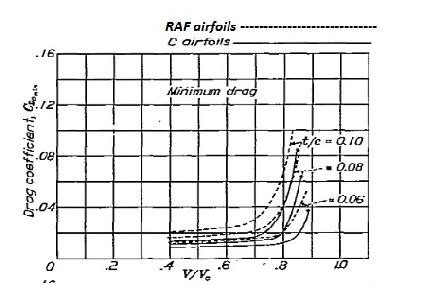
By coincidence, one of the aerofoils Stack tested in 1932 was RAF6, the Royal Aircaft Factory’s classic, reliable aerofoil from 1912, as used on the Curtiss Jenny. It was commonly used for propellers, and was adopted by DH in 1939 for the DP54409 blade specifically designed for the Whirlwind — despite being eminently unsuitable.
From the results of Stack’s work, published as The NACA high-speed wind tunnel and tests of six propeller sections in 1934, it was clear that the RAF6 section was the most vulnerable of the common aerofoils to what had become known as “compressibility drag”. Even at the precise angle of attack that produced the minimum possible drag, RAF6, modified to have a t/c ratio of 0·08, suddenly became extremely draggy at anything above 0·7 times the speed of sound. At 15,000ft in a climb the Whirlwind’s propeller blade-tips (at roughly 0·08 t/c ratio) were already through Mach 0·72. The drag on the props started creeping up, largely unnoticed at first.
While similar work had been done in the UK, especially on the mathematical side, there seemed to be some disconnect between theory and practice on this side of the Atlantic. Even as late as 1946 the Aeronautical Research Council (ARC) appeared to be re-inventing the wheel with a report from Farnborough’s 24ft (7·3m) windtunnel. The ARC’s Reports & Memoranda (R&M) No 2357 stated as plainly as a Royal Aircraft Establishment (RAE) tech paper could manage that between Mach 0·5 and 0·9, “it will be seen that [the rise in] minimum drag co-efficient increases steadily with blade thickness” — and profiles are not even considered in its comparison of blades.
The constant-speed prop
Here another potentially difficult concept comes into play; that of the constant-speed propeller. The aim of this development, also from the pre- war blossoming of aeronautical science, was to keep the engine turning at the optimum speed to produce the maximum horsepower. This it was required to do regardless of whether the aircraft was moving slowly, say on take-off, or at its maximum speed. This was done by changing the degree of the propeller’s “bite” — the angle of attack of the propeller blades. By increasing the blades’ angle of attack, drag is increased, thus creating a braking effect on the engine. To maintain constant r.p.m. at varying speeds, pitch is controlled, maintaining something optimum. If the engine begins slowing owing to increased drag, the blades’ pitch is altered to become finer. A constant-speed unit (CSU) automates this process. The desired r.p.m. is set; the CSU senses if the shaft-speed drops, and “fines” the blades appropriately (and vice versa).
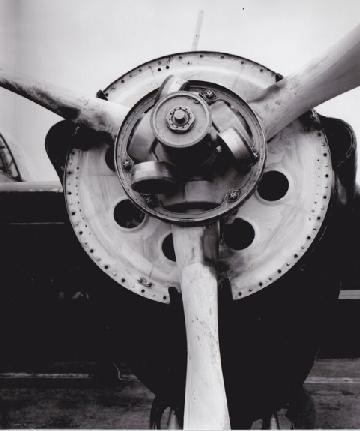
The Whirlwind had two DH constant-speed units under its sleek cowlings. When more drag — not profile drag as a direct result of the angle of attack, but from an external drag factor — is applied, the CSU turns the blades anyway. The system is “blind” to the cause, so when buckets of drag are dropped on a blade by compressibility as it hits a certain relative Mach, it “fines” in response. In their 1938 NACA paper The effect of compressibility on eight full-size propellers in the take- off and climbing range, David Biermann and Edwin P. Hartman were able to spin blades in airstreams and record the results. Once again the British RAF6 profile was tested, this time on 10ft (3·05m)- diameter BuAer profile 5868 blades of nine per cent thickness (measured, as was standard at the time, at 0·7 radius). This was so close to the DP54409 blade as to be practically a measure of a Whirlwind propeller in flight, except that it was thinner at 0·7 radius. (The WFP did actually measure a surviving Whirlwind blade to check this).
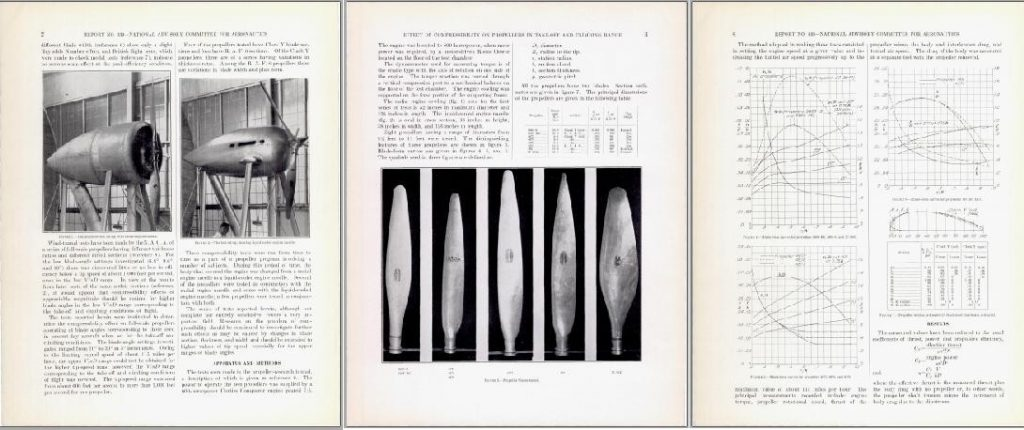
The prescient Biermann and Hartman made a point of testing controllable propellers on their rig, and, even more usefully, they tested RAF6 in this context and recorded the deflection of the blades required to attain a new optimum that maintains the desired r.p.m. In fact this only really came up with the RAF-section blades. They even made a note of the loss of thrust it incurred. In level flight there will be a steady drop-off in performance at higher altitudes, mainly because of the blade adjustment necessary to maintain r.p.m., but also owing to a slight decrease in efficiency. This is enough to make the maximum speed less than it should be (or would be with thinner and better-profiled blades), even as low as full-throttle height (15,800ft) and increasingly so above this. Interestingly, this effect of propeller profile and thickness on performance at full-throttle height had already been observed and carefully recorded in the UK, in joint tests conducted by The Air Ministry, Rolls-Royce, Rotol and Supermarine, intended to check propeller selection for the Spitfire Mk II.5
The results of trials with various propellers clearly showed a direct correlation between actual altitude at which maximum speed could be achieved around full-throttle height and thickness of propeller section. That this pointed clearly towards some effect was not commented on at the time, probably because it went against the belief that height of maximum speed was the same as height of maximum horsepower.
Practical application
In June 1940 Sqn Ldr Henry Eeles was tasked with working up No 263 Sqn on Whirlwinds, and that September he was asked by Air Officer Commanding Fighter Command Hugh Dowding (who may not have been entirely focused on the subject at that particular time) for his initial comments on the aircraft. After making it clear that the aircraft was quite special up to 15,000ft Eeles wrote: “It must be emphasised, nevertheless, that the performance of the Whirlwind above 20,000ft [6,095m] falls off rapidly, and it is considered that above 25,000ft [7,620m] its fighting qualities are very poor. The maximum height so far attained is 27,000ft [8,230m] but on every occasion that a height test has been carried out there has been a minor defect, either in airscrew revolutions or in lack of boost pressure.”1
Another summary of early experience with the Whirlwind, put together on behalf of No 13 Group (responsible for the air defence of Scotland, Northern Ireland and the north of England) as a report to the Air Ministry, mentions “boost- pressure variations”, but suggests this is down to the unreliable Exactor controls in the cockpit. There is no record of any unusual boost curve; nothing tabulated or charted on record. The only climb-curves for a production Whirlwind come from trials of P6997 with a 500lb bomb under each wing; boost “decay” looks entirely normal, and very similar to L6845. Unfortunately the data ends at 27,000ft. Returning to the theory, it appears that in a climb there is the potential for another, more serious problem to arise from thick, draggy blades; an effect caused by “hunting”, compounded by the blades’ twist being optimised for higher forward speeds.6
When an aircraft is climbing, the tips of the propeller blades are always at slightly too coarse a pitch, i.e. they “bite” more than necessary, so they cannot be at their lowest-drag angle of incidence. The greater the incidence, the greater the drag. As the Whirlwind ascends (more slowly than it would with thinner props), the speed of sound drops. All things being equal, the relative Mach over the blades increases, and more and more of the blade (moving inwards) “goes critical” as critical Mach itself lowers. At the same time the engine is losing horsepower, in the way one would expect of an aircraft climbing above full-throttle height.
As compressibility drag comes on exponentially, the CSU continually “corrects” the blade angle — hunting for a lower drag regime — possibly until it has gone through the minimum drag angle of the blades. Still not finding a low enough drag co- efficient to enable the 2,850 r.p.m. it needs on the reduced horsepower available, it does the only thing it can; keeps on reducing the pitch of the props, on into negative angle of attack.7
In this possible condition, P-factor (the effect of aircraft pitch) means that some parts of the prop are still pulling, others are being pushed. This would induce shockwaves everywhere, running up and down the blades as they spin, and no real net thrust being generated. Furthermore, wildly varying dynamic pressures would be passed into the ram-air intakes, which sit immediately behind the blades.8 The system becomes what a physicist would call “chaotic”. The intermittently windmilling prop produces fluctuating boost pressures on top of reduced r.p.m. To the hapless pilot this might look like an engine problem.
Whether or not this aerodynamic breakdown is what Eeles was describing as a “minor defect”, there is little doubt that the propeller blades chosen for the Whirlwind were much too thick, and must have had a serious effect on performance.
Proving it
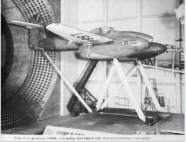
In 1940 the de-Havilland-bladed prototype, L6844, was mounted on pylons in the RAE’s 24ft windtunnel and thoroughly drag-tested.7 The unpublished Part III of the document relating to the findings still resides at The National Archives, and includes the only known record of the maximum speed of the prototype with the DH prop. It was 350 m.p.h. (563km/h). The report notes that windtunnel drag tests on the same airframe and some thrust calculations indicated that its top speed should have been 355 m.p.h. (570km/h) — similar to the Rotol-equipped L6845. The only way this could be accounted for was a difference between calculated and actual propeller propulsive efficiency.9
The report stated that this efficiency would need to drop from 77 per cent to 73 per cent to fit the actual top speed. Although the Farnborough scientists factored in compressibility on the blades, they did make one error; their calculations were based on a blade thickness of nine per cent (doubtless resorting to Biermann and Hartman for their figures, as the blades were so similar). However, the blades were 9·6 per cent thick in reality. This could be the simple explanation for the four per cent difference in propeller efficiency that was noted between calculated and actual.
With altitude, the problem could only get more serious. Above its own critical altitudes the performance drop-off curves of the Spitfire I were similar to that of the Whirlwind prototype. It is interesting to note that up to 10,000ft (3,048m) the Whirlwind (in service) climbed considerably faster than the Spitfire. While the DH blades of the two aircraft were similar, according to the RAE, the Spitfire’s DP55409 blade had been thinned by DH, to get a higher critical altitude and speed out of the fighter.10
Each of the Whirlwind’s Peregrines was faced with turning props against compressibility with less horsepower than a Merlin, but this was not because they were faulty. By the time later marks of the Spitfire and other types such as the North American Mustang were capable of more than 420 m.p.h. (675km/h) at altitude with two-stage superchargers and blade-tip speeds higher than Mach 1, the blades were of very thin section and NACA-developed profiles which negated compressibility drag, CSU correction and loss of thrust completely. A victim of indifference In hitting these limits, both the Whirlwind and the Spitfire ran into the issue of being faster than almost everything else.
The difference was, whereas Rolls-Royce, the RAF and de Havilland got together to work out how to make the Spitfire even better, nobody seemed that interested in helping out Westland with its baby. It seems a pity, with hindsight, that nobody thought to try thin blades on the Whirlwind (or even refit the Rotol design), rather than blame the engines.
Shortly after receiving Sqn Ldr Eeles’s report, Dowding made the decision to keep the Whirlwind away from any fighting in the south, sealing its reputation as the fighter that missed the Battle of Britain. In the very same correspondence in which he forwarded Eeles’ comments to Lord Beaverbrook, the Minister of Aircraft Production, he went on to say, “the limiting factor in the present fighting against Me 109s [sic] in the south of England is performance, manœuvrability and climb at high altitudes, and a difference in service ceiling of 2,000ft [610m] is a very important advantage. It therefore seems to me quite wrong to introduce at the present time a fighter whose effective ceiling is 25,000ft [7,620m]”.
Ultimately, the decision to discontinue production of the Whirlwind after only 114 had been built was an economic one. Rolls- Royce needed to concentrate on developing and producing Merlins and Griffons, and it was “extravagant” (according to Dowding) to produce a fighter that took two engines to do what another might with one. Nevertheless, it should be more than a footnote to say that, contrary to popular belief, the Whirlwind went on to serve for another three years, unaltered and very successfully, in the role of a low-level strike aircraft over the Channel and occupied France. And what of the Peregrine? In a letter addressed to the Air Ministry, dated September 24, 1940, Air Vice-Marshal Richard Saul, Officer Commanding No 13 Group RAF made it plain: “The Rolls- Royce Peregrine [used only for the Whirlwind] has given very little trouble”.
